Cyber Sculpt
Cyber Sculpt was a companion product for CAD-3D that provided expanded 3D geometry modeling capabilities. Cyber Sculpt had its own, elaborated “spin” and “extrude” modeling utilities, added a simple cross-sectional modeler, and provided an editing interface for vertex- and face-level modification. Geometry from Cyber Sculpt was saved to disk and loaded in CAD-3D for rendering and animation.
Immediately after the release of CAD-3D 1.0, some of its modeling limitations began to grate. A particular limitation was the inability to extrude font characters. There was a market demand for 3D fonts, but CAD-3D couldn't extrude a shape with a hole in it. Letters such as “O” and “R” were impossible to create without using messy Booleans. In order to develop his 3D Fonts I product, which contained a basic serif font and a basic sans-serif font as CAD-3D geometry, Tom created a small stand-alone utility called the Super Extruder Tool. The Super Extruder could handle those holes, and the utility ended up being included on the fonts disk as a bonus.
When it came time to do CAD-3D 2.0, another problem arose: memory. There was a direct trade-off between the number of features that could be included in CAD-3D and the memory that remained to hold, manipulate and render the user’s 3D geometry. The priority for CAD-3D 2.0 was animation, so the new CAD-3D retained its predecessor’s extrusion limitations.
Tom eventually created Cyber Sculpt to significantly advance CAD-3D’s modeling capabilities, and it is one of the most sophisticated pieces of software ever written for the ST. Again, for memory reasons, Cyber Sculpt was kept as a separate application from CAD-3D, instead of being CAD-3D 3.0.
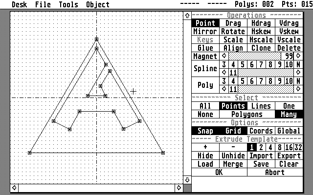
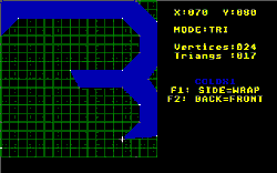
Cyber Sculpt’s Extrude template editor showing an extrusion template of nested shapes (the letter “A” will be negative space)

One of the biggest challenges for Cyber Sculpt was becoming more sophisticated about the 2D templates that are used in extrusion and lathe modeling. In Cyber Sculpt, these templates were shapes drawn by the user and defined by connected points. The shapes had to be closed (not open-ended) and the lines could not cross, but the shapes could otherwise take any form and be nested inside each other (to create holes). A template in action is one of the more intuitive concepts in 3D computer graphics—for a human. Computers, on the other hand, are intuition-free, and templates create a lot of ambiguities. Tom explains,

Keying a shape vertex
At the time, the nested extrusion templates were a big deal for me. It was a challenge to handle the connection of dissimilar templates, and I think we came up with a pretty solid method, using “keys” to relate vertices on one template to those on another.
Keys were actually a simple solution to a complex problem. Keys enabled the user to tag vertices (points) in their shapes with numbers so the computer didn't have to guess.
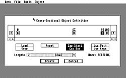
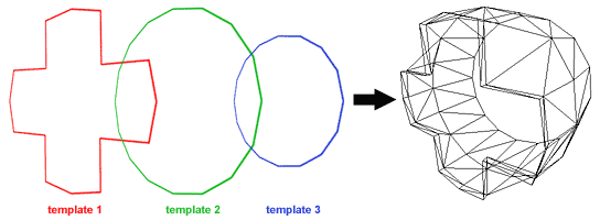
Solving the nesting problems opened the door for one of Cyber Sculpt’s entirely new features: cross-sectional modeling. Technically, cross-sectional modeling was first possible using Cyber Control, which could be used to algorithmically create geometry (see Darrel’s Design Disk work). Cyber Sculpt brought this capability into a GUI. Sort of. Interactive cross-sectional modeling has never been (even today) all that easy to do in 3D software, and few really mastered this aspect of Cyber Sculpt. Nonetheless, with good planning it was possible to build representations of car fuselages and such in Cyber Sculpt by positioning cross-sections and relating them with keys. The main technical limitation—which would be addressed in 3D Studio—was that Cyber Sculpt couldn't interpolate between templates; it could merely connect them.
The other major new feature in Cyber Sculpt was the 3D editor, which enabled the user to push, pull, poke and prod 3D geometry at the lowest level. Conceptually, the 3D Editor extends the same move/rotate/scale/delete functionality that applies to entire objects in CAD-3D to the vertex structure of a single object. Operating the 3D Editor was simply a matter of selecting the vertices one wanted to manipulate, then selecting and applying a manipulation tool.
An impressive—though not frequently useful—feature of the 3D Editor was a magnet tool, which could be used to distort groups of vertices as if they were being attracted to the mouse position.
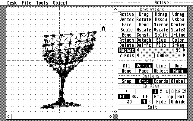
Cyber Sculpt’s 3D Editor showing the magnet tool distorting the shape of a wine glass
The design of Cyber Sculpt is notable for its modal nature. Unlike CAD-3D, which provides a constant window on its 3D universe, Cyber Sculpt is just a blank screen when you first start it up. The 3D universe is there, but it’s invisible until you enter one of its modules. Inside the Spin and Extrude modules, the view is strictly 2D for editing a template. The cross-sectional module is really just a dialog box for ordering templates. Furthermore, the 3D Editor never shows the universe from more than one dimension at a time.
There were two major reasons for these limitations: one was simply screen resolution. Cyber Sculpt was all about precision work, so it didn't make sense to chop the Atari’s already-limited resolution screen into little windows like CAD-3D. The other reason was that, unlike CAD-3D, which concerned itself with issues of gross scene composition, Cyber Sculpt was concerned with the precise adjustment and definition of 3D forms. The convenience of having four active views of the geometry was outweighed by the practical need for higher-resolution local control.
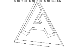
The one way the user got to visualize his work in 3D from within Cyber Sculpt was with the interactive 3D view, which would render a wire frame camera view of the currently-resident geometry under “real-time” mouse control. Due to the processing limitations of the ST, however, this interactive 3D view was only responsive with simple objects.
Despite its limitations, Cyber Sculpt was a major augmentation of the 3D capabilities of the Cyber software. Metaphorically, modeling in Cyber Sculpt was somewhat like moving from Legos to a carpentry shop.
Postscript: Cyber Sculpt after the Atari
CyberSculpt was the last product Tom Hudson produced for the Atari. At the time of its publication, he had already moved on with Gary Yost to begin development of MSDOS-based 3D Studio for Autodesk. However, Cyber Sculpt also provided the basis for developing 3D Studio.
In addition to contributing various algorithms, Cyber Sculpt’s distinctive modal approach to the 3D scene was adapted for 3D Studio, which was divided into three primary modes (plus a materials editor): 2D Shaper, 3D Lofter and 3D Editor. The 2D shaper was very similar to the Extrude and Spin template editing views of Cyber Sculpt. The 3D Lofter combined extrusion and lathe functionality with significantly more sophisticated parameterization and a flexible, visually-editable 3D path. The 3D Editor of 3D Studio incorporated both the multi-view scene manipulation functionality of CAD-3D and the vertex editing features of Cyber Sculpt’s 3D Editor. (The new VGA standard of the PC nicely alleviated the screen resolution crunch of the Atari, and made many more colors available.)
The modal approach begun in Cyber Sculpt proved attractive for compartmentalizing functionality, keeping workflow conceptually simple and easy to explain, and most importantly, for best leveraging the relatively limited processing power of both the Atari STs and the PC-compatibles of those years. The downside was that modeling had to be done out-of-context from the scene one was working on. With 3ds max, the modal approach was abandoned, bringing that software more into line with products like Alias, where modeling could be done within the 3D scene itself.
Path
A path is a mathematically-defined (usually drawn by the user) route through two or three-dimensional space that the computer will use for some purpose. In 3D computer graphics, paths are most commonly used either to dictate the movement of an object within a scene or to provide a flexible axis on which the object’s own geometry is built.
Vertex
A point in space, defined by numbers, of two or three dimensions. Vertices are a fundamental building block of 3D computer graphics.
Face
A set of three or more vertices connected to represent an arbitrary surface (or more commonly, a facet of a surface). Faces are a ubiquitous building block of 3D computer graphics.
Boolean modeling
Boolean join algorithms take two or more solids that intersect each other in space and either merge their surfaces, subtract one volume from the other, or discard all but the shared volume. In this example, a hemispherical indentation is made in a block by subtracting a sphere from it.

Spin
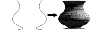
Spin, more commonly known in computer graphics as “surface of revolution”, was a lathe-like tool where the user draws a symmetric cross section which the computer uses as a profile for a cylindrical form.
Extrude
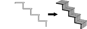
As it sounds, extrude was a tool that took a user-drawn cross-section and built geometry that gave the shape depth.
Rendering
In computer graphics, rendering is the process of algorithmically deriving a picture or piece of a picture from other information, which may be a view of 3D geometry, 2D geometry (line art) or other picture information.
Spline
A smoothly curving path (in two or three dimensions) through space calculated from three or more fixed points, often specified by the user.
User Interface (UI) and Graphical User Interface (GUI)
Computer programs don't actually do anything visible to the user unless the programmer goes out of the way to include visual features. These features, which often the user can interact with through a mouse or keyboard, constitute a user interface. Graphical User Interfaces further infers a level of visual sophistication in the interface beyond computer terminal text.
